Home Page |
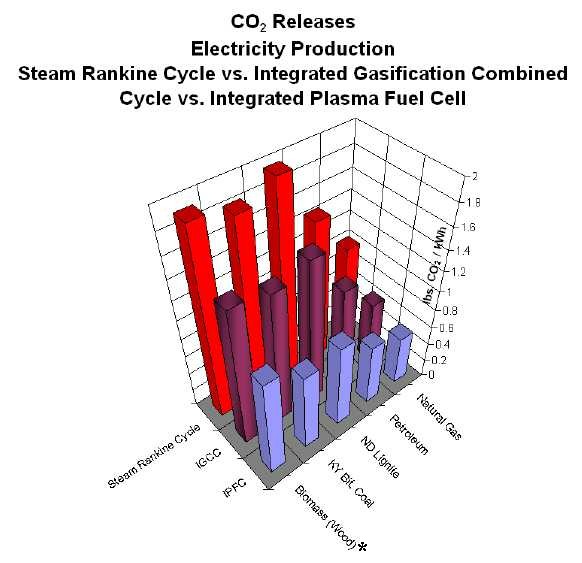
CO2 Comparison Chart Large-Scale Integrated Plasma Fuel Cell Process Plant
 The above carbon dioxide comparison chart illustrates carbon dioxide releases for electricity production from three different types of plants using five different fuels. As can be easily seen in comparing the heights of the columns, the largest producers of carbon dioxide gas are electricity plants using traditional Steam Rankine Cycle technology, the technology commonly used throughout the United States. This is represented by the red columns, which are the tallest columns at the rear of the chart. Next lower in carbon dioxide production are advanced Integrated Gasification Combined Cycle plants, which are considered the cleanest advanced combustion technology for new fossil-fuel power plants. This is represented by the maroon columns in the middle row of the chart. Finally, the lowest columns at the front of the chart illustrate a still lower volume of carbon dioxide production calculated for a full-scale Integrated Plasma Fuel Cell Process plant. This is represented by the blue columns. Concentrated carbon dioxide production volume from an Integrated Plasma Fuel Cell Process plant is projected to be about half that of current generation coal burning plants and significantly less than from advanced Integrated Gasification Combined Cycle plants. In stark contrast from the other two plants, the carbon dioxide from an Integrated Plasma Fuel Cell Process plant is not mixed with other combustion pollutants. Instead it is a concentrated carbon dioxide product resulting from the fuel cell combination of carbon and oxygen. Thus, unlike existing technologies, an Integrated Plasma Fuel Cell Process plant potentially makes carbon dioxide a marketable commodity. In concentrated form, it can be marketed to improve production from oil wells, to initiate methane emission from coal beds, and to use in a growing food and beverage market. In addition, a lesser volume of carbon dioxide from an Integrated Plasma Fuel Cell Process plant potentially lowers the cost of sequestration and makes the plant a candidate for zero carbon dioxide emission. *Note on Biomass. For biomass, the columns in the chart indicate the relative carbon dioxide emissions from a power cycle. However, because photosynthesis consumes atmospheric carbon dioxide in the growth of the biomass, its subsequent consumption actually produces minor net carbon dioxide emissions to the atmosphere. The minor net emissions are attributable to the fossil fuel needed to cultivate the growth of the biomass. The numbers for biomass fuel are relevant because they show that using the Integrated Plasma Fuel Cell process would consume far less biomass for the same electrical output. This, however, is more an economic consideration. Last modified 07-MAY-2011
|